Chapter 5. Android Software. Input Controller service
Linked repositories:
Welcome to our article on the inner workings of the most complex software system in the Pinect game controller! As the technical lead of this project, I have had the opportunity to dive deep into the inner workings of this system and I am excited to share my insights with you.
In this article, we will delve into the details of the complex software that powers our game controller, enabling users to input commands and play various games on the device. This software is made up of several android services that interact with each other in order to provide the necessary functionality for the controller to work properly. We will explore the specific roles that each service plays and how they communicate with each other. We will also discuss some of the challenges that we faced while developing this software and how we overcame them.
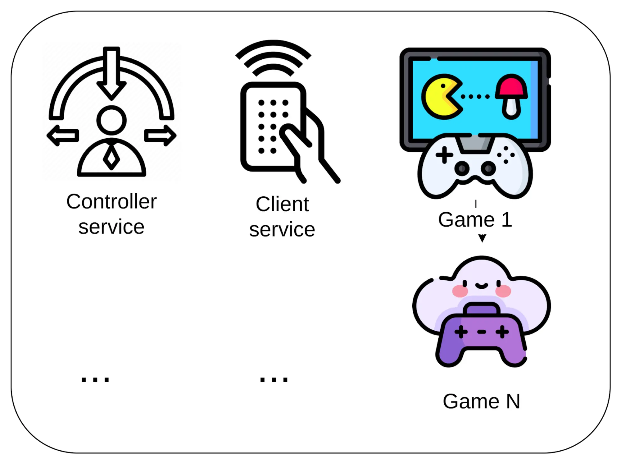
In order for a tablet to run a game, it must have at least three android services installed. These services work together like a microservice architecture to provide the necessary functionality for the tablet to run the game, capture input commands using the camera, and execute remote commands.
The first service is the controller service, which handles input from the camera and processes it into meaningful commands that can be passed to the game.The second service is the client service, which is responsible for executing remote commands and sending game stats to the server. The third service is the game, which runs the actual game and handles the gameplay mechanics. There can be many different games that can be run on this system, and developers can even create their own custom games to run on the platform.
Let’s take a closer look at the controller service, which is an android app responsible for handling input from the camera. It captures images from the USB camera and processes each frame to extract meaningful commands that can be passed to the game. However, the Opensource UVC camera library only allows for the drawing of frames, and does not provide access to the raw frame data. In order to capture and process the raw frame data for our purposes, I had to patch the library by adding a new native endpoint that sets a callback function. This callback function accepts the raw frame data as an argument, allowing us to access and process it as needed. We then set the callback and wrote our own code for processing the frame data.
In this function, the code repeats the operations described in a previous post. Briefly, These operations include:
- Converting the image to grayscale
- Applying a predefined mask to the frame to extract data
- Summing the data in each column
- Processing the summarized data
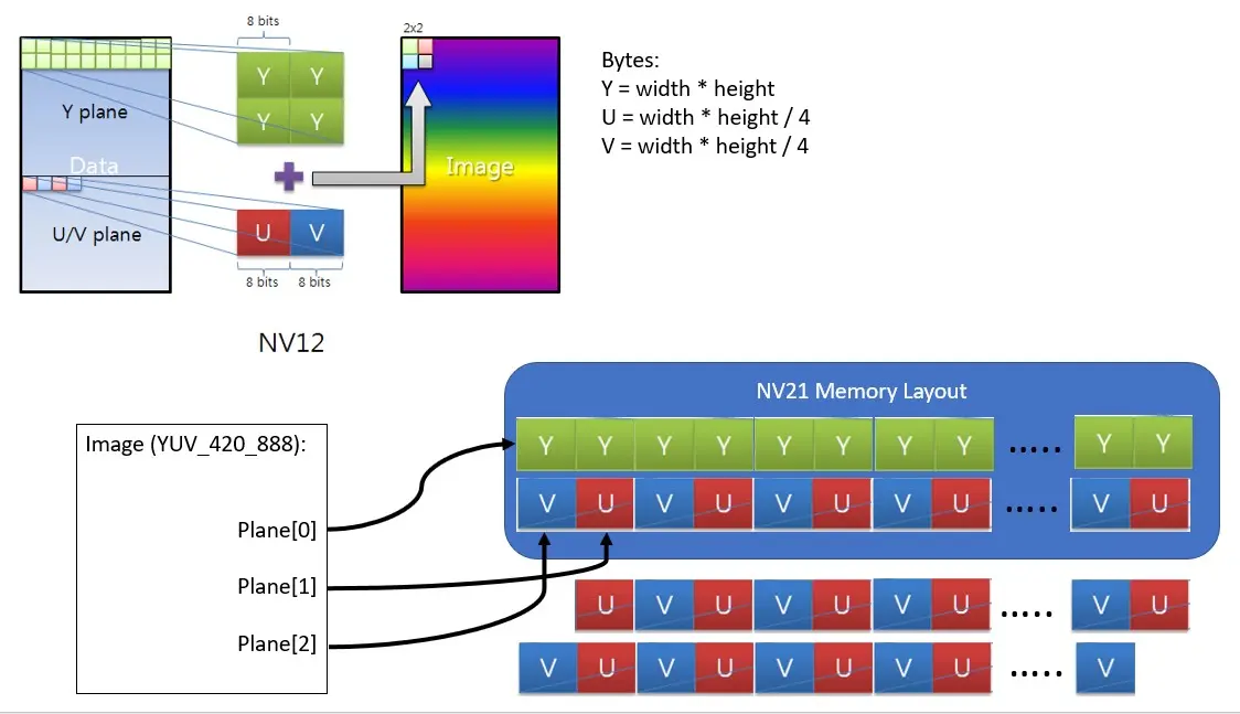
The first and second operations have been optimized by taking advantage of the YUV format of the frame, which consists of two bytes per pixel. The first byte is the brightness, and the second byte is the color. By extracting data using the mask and only taking the brightness byte from the frame, we can skip the color byte and save processing time.
The third operation involves summing the data in each column to obtain a summary of the relevant information. The fourth operation involves processing this summarized data to recognize the player’s stream position. The specific approach to processing the data depends on the state of the program, with different steps being taken at different times. For example, at the start of the program when it is being trained, a reference dataset is calculated that will be used to compare against future data. Once the reference dataset has been crafted, the app can start to recognize the player’s stream position.
Let’s try out the app and see how it works. Source code repo
You can download the pilauncher.apk from here or build the app using this guide. Install it and run it.
Note that this software was custom-built for the Huawei Mediapad T3(Android 7), so if you run it on other devices or emulators, you may experience different or incorrect behavior.
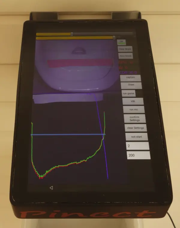
When you run the app and connect the USB camera, the debug screen is launched. On this screen, you can set up various options, set the mask, run various modes, and view debug information. On this screen, you can set up various options, set the mask, run various modes, and view debug information. As mentioned in the first post, you have to set the mask for the area search on this screen before starting the player’s stream position capturing. To set the mask, follow these steps:
- Press “Clear Mask” to clear any existing masks in the app.
- Touch on the area of the screen that you want to mark as the search area. This will create a mask that outlines the region of interest.
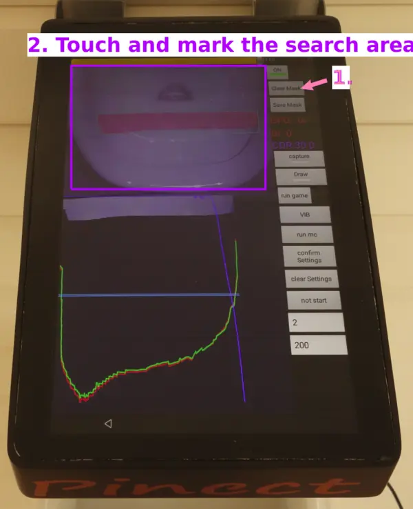
This allows you to specify the region of the frame that the app should focus on when recognizing the player’s stream position. You can use this feature to fine-tune the app’s performance and ensure that it accurately recognizes the player’s stream position even in challenging environments.
Once you have set the mask, you can run the provisioning mode to collect data and calculate the reference dataset. To start the provisioning mode, toggle the marked button on the debug screen. This mode, called “learn” in the app,
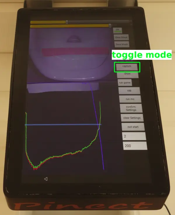
After you have recorded enough data, the app will automatically calculate the reference dataset and store it for future use. You can then switch to the capturing mode to test the app’s functionality and observe the results. To toggle this mode on, simply press the button. This mode allows you to see the app’s output in real-time, giving you a sense of how it is performing. You can play with moving and look at the calculated position in the app, just like in the video.
Unfortunately, no video demonstration of the mask setting and provisioning mode has survived.
When the app is running, the screen displays various pieces of information that can help you understand how it is performing. The bottom part of the screen shows graphs of the reference dataset, the current data in real-time, and their difference, which has been processed by the app.
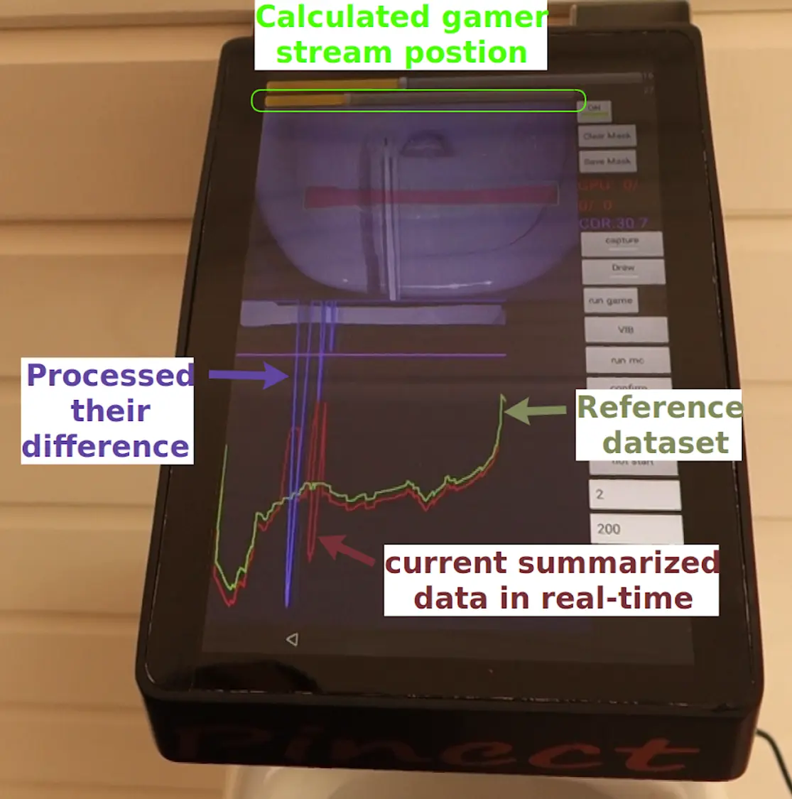
The seek bar on the top part of the screen shows the calculated player’s stream position, as determined by the app based on the data it collects and processes from the camera. The seek bar is a graphical representation of the player’s stream position, with the left side of the bar representing one end of the range and the right side representing the other end. The position of the thumb on the seek bar reflects the player’s current position within this range.
In the next post, you will discuss the game and how the controller service passes the resulting player’s stream position to the game. You will also touch on the development of your network game. It will be interesting to see how the various components of the system work together to enable users to run games on the controller.