Chapter 3. Control Board
Linked files:
In my previous posts, I explained an algorithm of recognizing the gamer stream for the Pinect hand-free console and the design of the finished device. In this post, we’ll look at the control board design.
Note: it’s worth noting that the control board is not a mandatory component for running the Pinect software on an Android device. The control board does automate various tasks, it’s not strictly necessary for the software to function. The Pinect software can still be run on an Android device without the control board, although the gaming experience may not be as seamless or intuitive.
The control board for the Pinect hand-free console is an essential component that is responsible for performing a variety of tasks. As you mentioned, some of the main tasks that the control board is responsible for include:
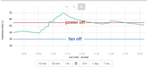
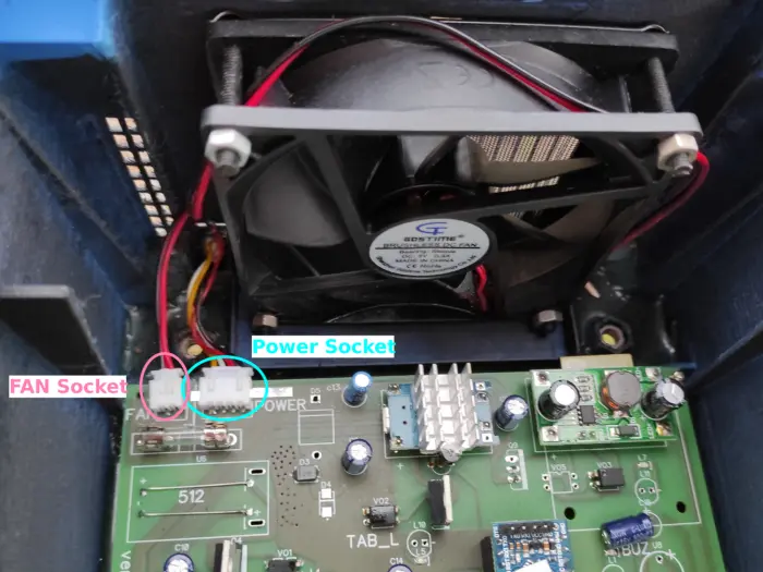
- Managing and monitoring the temperature of all the electronic components. The control board is equipped with a temperature sensor and a fan to ensure that the components are not overheated and that they function properly. The temperature sensor is used to monitor the temperature of the most heat-sensitive electronic components like LED, driver, and the tablet. By constantly monitoring the temperature of these components, the control board can detect when the temperature is getting too high and take appropriate action.When the temperature exceeds a certain threshold, the control board will turn on the fan to cool the components. The fan circulates the air around the components, dissipating the heat and lowering the temperature. The control board will turn off the fan when the temperature drops back to a safe level. It’s worth noting that overheating can lead to damage in electronic components, which is why it’s important to ensure that they are running at an optimal temperature range
- Handling a signal from the motion sensor: The control board is responsible for receiving and processing signals from the motion sensor, which is used to detect the presence of a gamer. When the motion sensor detects movement, it sends a signal to the control board, which can then trigger certain actions, such as turning on the camera and LED.
- Turning the camera and LED on and off when necessary: The control board is also responsible for controlling the operation of the camera and LED, which are used to capture the gamer stream. The control board can turn these components on or off based on signals from the motion sensor or other input.
It is important to optimize the energy usage of the Pinect hand-free console, especially since the tablet, camera, and LED are all power-hungry components. One way to do this is to ensure that these components are only active when a gamer is ready to play. When no one is around, the tablet can be put into standby mode, but the camera and LED should be switched off completely. This will help to conserve energy.
To achieve the fastest user interface reaction, it is also important to activate the console seconds before the game, so that the gamer can start playing right away. This can be done by using motion sensors to detect when a gamer is approaching the device. The motion sensors will send a signal to the control board, which can then wake the tablet up from standby and turn the camera and LED on.
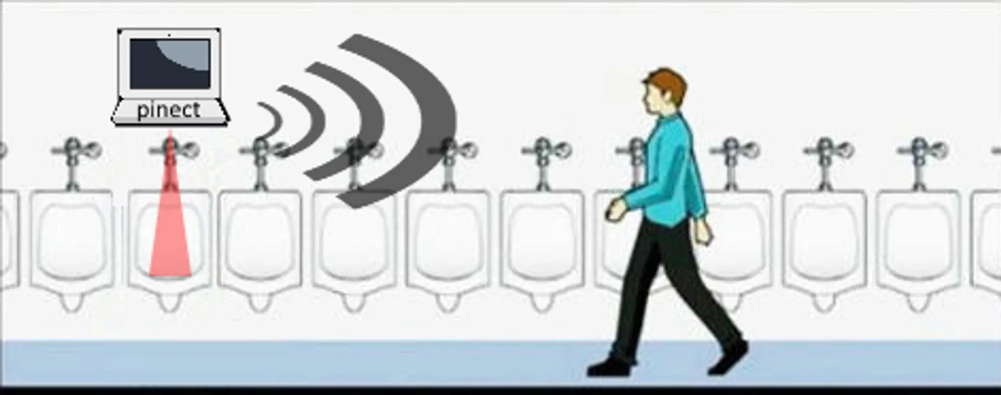
By using motion sensors to detect when a gamer is approaching the device, we can ensure that the Pinect hand-free console is always ready for use and that the gamer has the best possible experience. This is an important aspect of the device’s design and helps to ensure that it is efficient and user-friendly.
The sensor can detect when a gamer approaches the console. It gives a simple logical signal. This signal is handled by the control board, which activates all electronic components:
- Camera
- Power supply of the tablet
- LED
- Fan
- Sensor
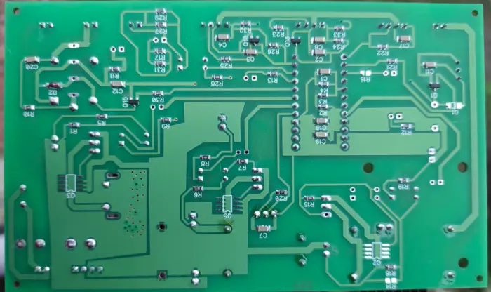
The control board is presented here
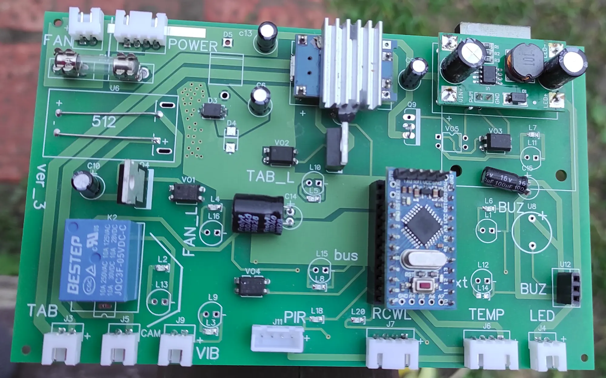
bottom view:
That’s correct, the Pinect hand-free console uses a 5V power supply and the tablet’s USB port was disconnected, so power cannot be supplied through the USB socket. In order to supply power to the tablet, a battery charger, specifically TP4056, is used. The TP4056 is a widely used and inexpensive charger that can be easily integrated into the control board.
The output of the TP4056 charger connects directly to the tablet’s battery. This is important because the tablet’s battery is designed to accept a specific voltage and applying an incorrect voltage could damage the device or even cause a fire hazard. By connecting the charger directly to the battery, we ensure that the correct voltage is applied to the tablet.
Additionally, the charger has protection and monitoring functions such as over-current, over-voltage, over-temperature and short-circuit protection. This added level of protection to the battery will ensure a stable power supply and prolong the battery’s life.
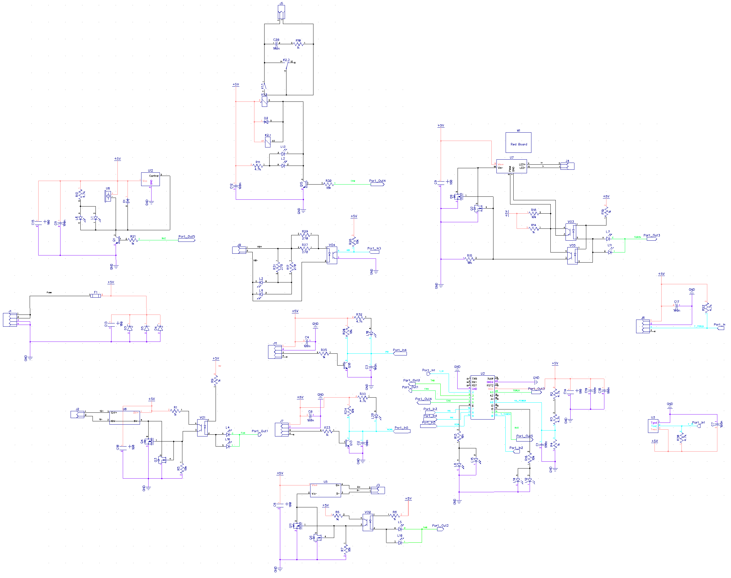
You can download the circuit diagram here. And PCB layout here. All files have a DipTrace file format.
In the scheme and layout, you may notice that some of the electronic parts are not soldered onto the PCB. This is because I have included spare parts on the diagram and layout, For example:
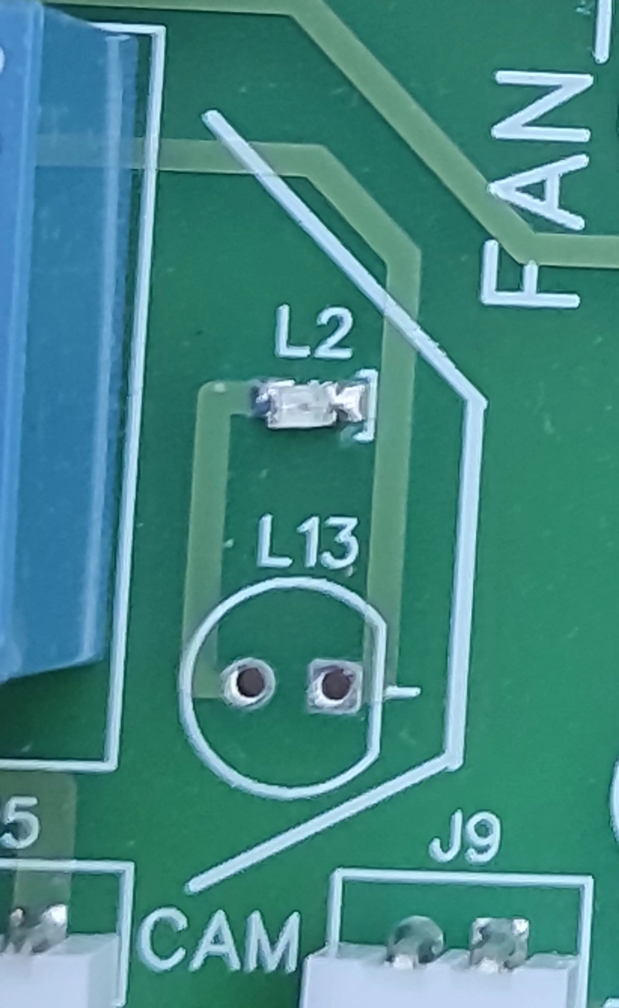
L2 and L13 LEDs are in parallel. You can also choose between using SMD or DIP versions of the LED depending on what you have available
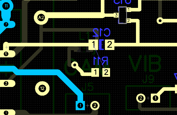
Explain all of the connectors and their functions on the control board.
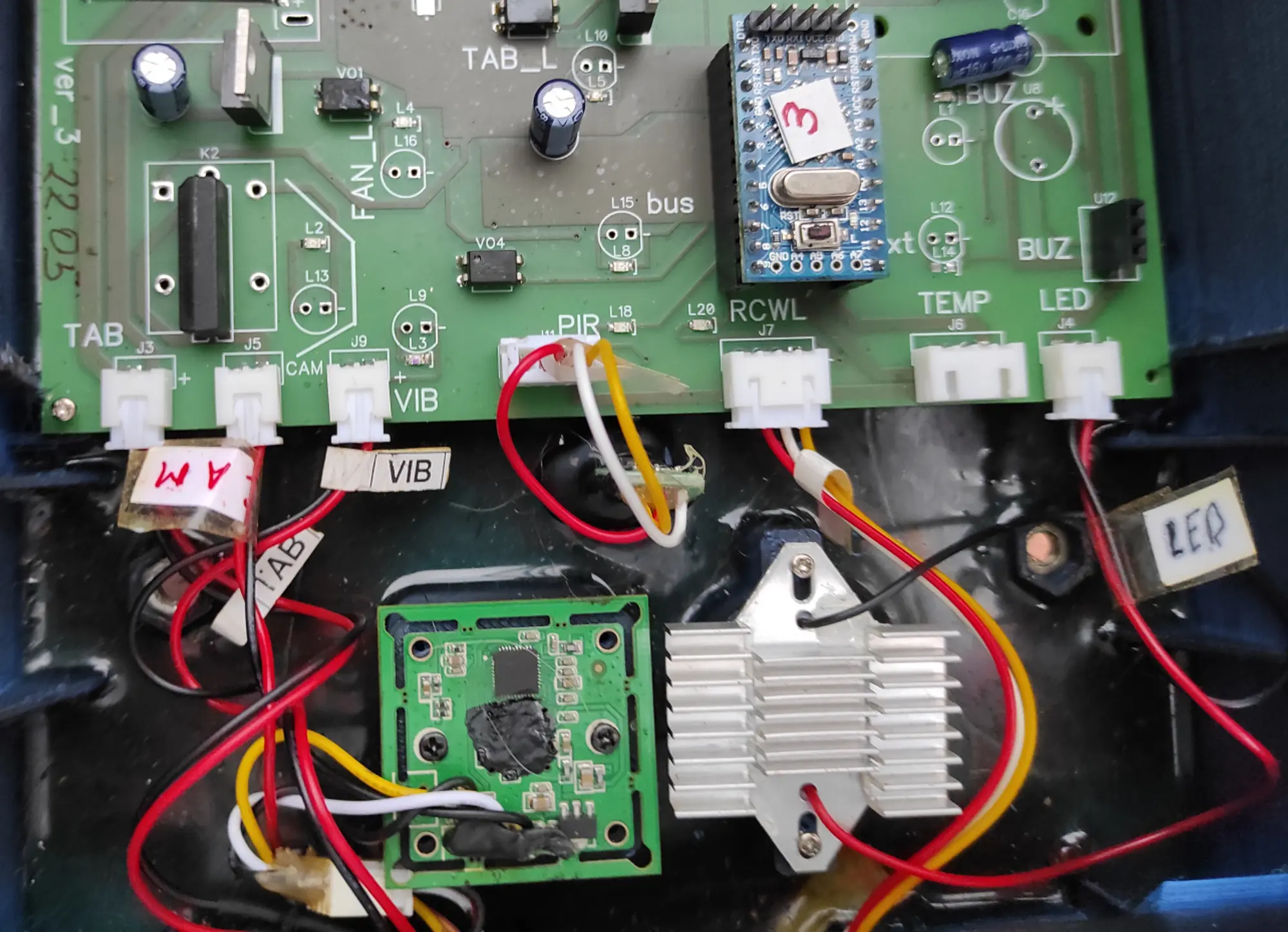
The “TAB” J3 socket is a power connector for the tablet. The tablet’s battery is charged all the time.
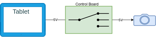
The “CAM” J5 socket is used to connect power to the camera, and the control board uses the K2 relay to control the flow of power to the camera. The “VIB” J9 socket is used for the tablet to send feedback signals to the control board.
The PIR motion sensor is connected via the J11 “PIR” socket. By analogy, The radio motion sensor is connected via the J7 “RCWL” socket.
The J4 “TEMP” socket is used to connect the temperature DS18B20 sensor. This sensor is attached to the finned heatsink of the LED (The photo above doesn’t show it).
The J4 “LED” is a power connector for the LED diode.
All the control circuits are galvanically separated from the Arduino controller with the optocouplers.
Optocouplers, also known as opto-isolators, use a light-emitting diode (LED) and a photo-sensitive device to transfer electrical signals between circuits. This allows for complete electrical isolation between the input and output side of the optocoupler, thereby breaking any ground loops and preventing any unwanted interference or noise.
We have taken an in-depth look at the Pinect control board and all of its features.
In the next article, we will explore the firmware that powers the Pinect control board. As the software backbone of the board, the firmware plays a vital role in its operation and functionality. Understanding the firmware can open up a world of possibilities for customizing and optimizing the control board to suit your specific needs.